
| Click for larger |
 |
 |
|
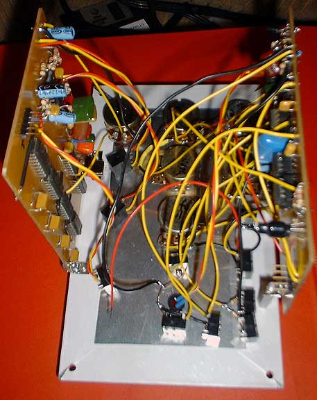
I created this circuit with the "best of" ideas after doing two other S&H circuits. I wanted this module to be a self contained substitute for a keyboard, therefore it needed to provide CV, Gate, and Trigger outputs. Variable width gate was something I missed from the Lockbox Synth S&H. The LED gives a visual indication of both the LFO rate and gate width. I wanted it to be a self contained substitute for a keyboard, so it needed CV, Gate, and Trigger outputs, and an internal clock.
Ultra Sample and Hold schematic How it worksThe "clock" is a standard tri-square VCO built around OTA U6, integrator U5, and Schmitt trigger U2. The exponential converter is a simplified one built around Q1 and Q2 since it didn't need to track anything. The output of the triangle waveform is brought out through the LFO level pot and the LFO jack. The External Clock input takes advantage of a jack with a normally closed switch. The internal LFO is fed to the jack switch and so becomes the External Clock input when no plug is inserted. Inserting a plug opens this connection, and so the signal on the plug becomes the External Clock input. Note: "Clock" is a bit of a misnomer, since it implies a digital type signal (i.e., a positive pulse). This input should actually be driven with an LFO waveform that has slopes (saw, tri, or sine), and about +/- 5v amplitude, for the variable gate to work. You can drive it with a digital type signal if you adjust the Width control until you see the LED come on, but the Gate width will be the same as the clock width. The triangle waveform also drives a PWM ciruit built around comparator U3:A. By comparing the LFO waveform to a voltage from the Width pot, the output is a variable width positive gate at the frequency of the LFO. Note that the LFO upper and lower limits should be less than the Width pot voltage range or you will get no Gate out at the Width extremes (mine is adjusted for about 10% to 90% gate width). The Gate is brought out to the Gate jack. It also drives the Darlington pair Q3 and Q4 to drive the LED. The trigger output is derived from the gate by first inverting it with Q5, then driving a monostable (one-shot) built around the other half of the LM319 comparator, U3:B. This outputs a one millisecond pulse on the negative edge of its input (that's why the inverter Q5 is needed. We want the trigger to coincide with the rising edge of the gate. I originally left this off the PCB and had to kluge it in). The trigger is brought to the Trigger output jack. It also serves double duty as providing the Sample control to the LF398. The Sample & Hold input is wired to the White noise output Pseudo Random Noise module via another N.C. jack. Therefore, plugging a patch cord into this input overrides that connection. The input goes through a one pole lowpass filter made up of U1:B, U1:C, and the SLEW control. This will limit the peak voltage excursions as you filter out higher frequencies (mainly for use with a Noise input). In the minimum position is has about a 3400 Hz cutoff. The Sample and Hold itself is the National LF398. For a Synth S&H you want to have a very short Sample control to acquire a new voltage, then hold it. The 1 mSec Trigger provides this. The output goes through another one pole lowpass filter made of U1:D and the GLIDE control, for portamento effects. |