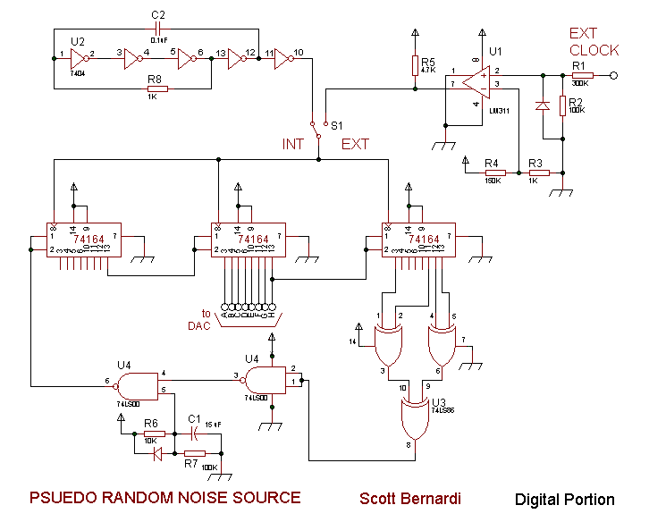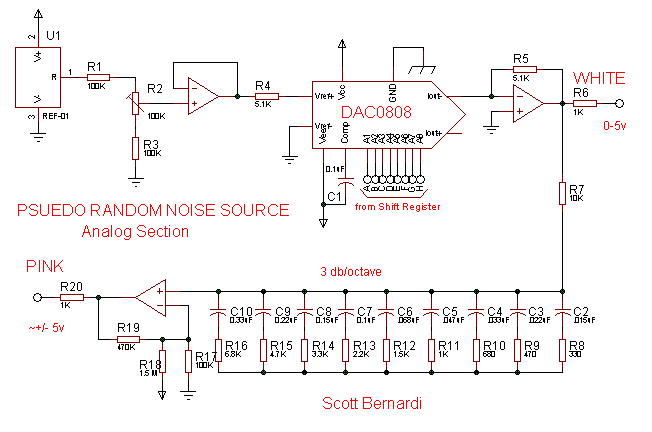

Parts substitution/simplification:
The REF-01 is not necessary. A voltage divider or zener reference to
provide a 5v output to the buffer U1 would be sufficient. I just happened to
have access to the REF-01's for free.
Any 8 bit linear DAC can be used. I actually have a DAC312 in my circuit,
using just the most significant 8 bits (again, I had free access to them).
You can probably skip every other pole-zero pair in the -3db/octave
network for the Pink Noise output and still get acceptable results.
I built this circuit after frustrated with trying to get decent results out of circuits that generated noise from a transistor BE junction in reverse breakdown.
The noise output makes a great input to run through the Sample and Hold, then feed to an oscillator, or a Hi-resonance lowpass filtered waveform.