Potentiometers and trimpots can really run up an expense in DIY synth building because you will use so many of them. So when it becomes possible to obtain a number of them cheap, it is a good idea. But then you run into the problem that you have 20 of these pots or trimpots you got for a great deal, but a schematic calls for a different value. When can substitutions be made?
Typically pots come in two "tapers", which describe the resistance vs. % rotation curve.
Log pots are almost always used for controlling volume, or gain, or level - the ear responds logarithmically to changes in loudness, so a log control is necessary to make the increase in volume sound "smooth".
For an excellent tutorial on potentiometers, see R.G. Keen's The Secret Life of Pots.
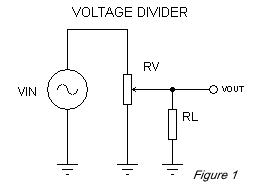 One of the most common configurations for pots are to be hooked up as a
Variable Voltage Divider (Figure 1). With a linear pot for RV, Vout will be linearly proportional to Vin providing the pot value is 10 times
less than the load resistance represented by RL. As RL approaches the value of RV, the Vout to Vin response is "warped".
The best way to see the effects of pot loading is via a nifty little Java applet written by Christopher List.
Here is a good opportunity for part substitution. As long as you obey the rule that the pot value << RL/10, you can use any value for the pot. If you can stand a little warping, you can go up to a pot value of 5 times less than RL.
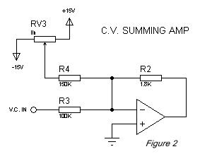 There are some limits to how low you can go with a pot value if you are using it to divide a
voltage down, due to power disspiation in the pot. In Figure 2, a typically control voltage summing amplifier, the full 30v of the plus
and minus power supplies are across RV3. The << RL/10 rule would give a value of 15K for RV3. You could substitute a 10K pot easily.
But what if you had a 1K pot? That is a problem, because the power dissipation would be (30)^2/1K = 0.9 watts.
You can play some tricks here. Let's say you want the pot to give you the equivalent of a +/- 10v adjustment range. In an inverting summing amplifier, you are really summing input currents. The V.C. In input has a 100K resistor, so the input current for a 10v range would be 10v/100K = 100uA. Note that the choice of +/- 15v across the pot with a 150K summing resistor gives the same 100uA.
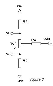 But let's say you just have to use your 1K pot for RV3. You can put some resistor in series with it,
so that less voltage is dropped across RV3 (Figure 3). Say we want +/- 5v dropped across RV3 for a total of 10v, and so you need to drop another
10v across R5 and R6. Therefore we can make R5 and R6 1K also. The power dissipation in RV3 will be (10)^2/1K = 0.1 watt, which is fine
for a typical 0.25 watt pot.
Now to get the +/-5v across RV3 to give the 100uA, we half R4 to 50K (49.9K, or for Initial Value type controls, 51K is probably OK).
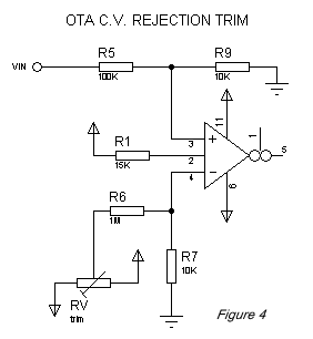 For trimpots, where the value of the pot will be adjusted once and then left, obeying the pot value << RL/10 rule is less
important. In Figure 4, a typical control voltage rejection trim circuit for an OTA, the value of the RV trimmer could be made equal to the load
resistance R6, which would warp the rotation vs. resistance curve, but it really doesn't matter since you are setting the value once.
Square Law Attenuators
The figure below illustrates another way to approximate logarithmic attenuators using dual linear pots. In the first circuit, we get a nice log/audio taper. It is actually a square law, but it has a nice "feel" to it. The second circuit is an inverse sqaure law attenuator (notice it's the configuration of the first circuit flipped upside down), and is probably the more useful of the two because it approximates the reverse log taper - and reverse log pots are hard to find.
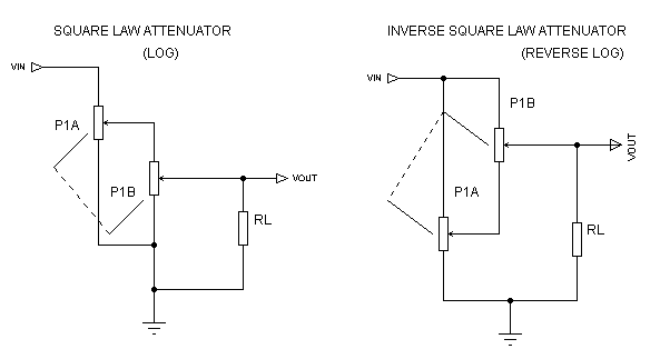
Use similar rules about keeping the load resistance RL 10 times the value of the pot to minimize loading effects.
For the square law attenuator, The equivalent resistance presented by the network (as seen by Vin) varies from Rpot || RL when the pot is at 0% rotation, to Rpot when it is at 100% rotation.
For the inverse square law attenuator, The equivalent resistance presented by the network varies from Rpot || RL when the pot is at 0% rotation, to Rpot / 2 when it is at 100% rotation.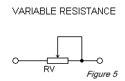 The other most common type of configuration for potentiometers is just to hook it
up as a Variable Resistance (see Figure 5). In a common circuit such as a gain adjustment (see Figure 6), you can
change RV1 as long as you keep the ratio RV1/R8 the same. In a gain control circuit, you'll want to use a log taper pot for RV1.
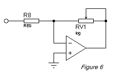
When using a trimpot for a variable resistance, you can substitute a larger value, but you lose trimming resolution. That is, the same rotation causes a larger change in resistance, hence it is harder to "fine tune". One way to compensate for this is to use a multiturn trimpot (of course these are more expensive).
You can use a lower value trimpot and add a resistor in series with it. This will keep the same maximum value of resistance, but will decrease the range of adjustable resistance. But at the same time, it increases the resolution, which can be a good thing. For example, say you had a variable resistance that you expected would trim to somewhere between 20K and 40K. You could use a single 50K trimpot, or you could use a 20K trimpot in series with a 20K resistor, which would give you easier fine tuning.
Variable Control Voltage Circuits
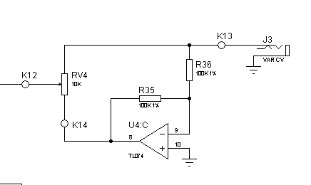
Here is a circuit that I find especially useful when you want to have a control voltage that you can invert, as well as continuously variable. A prime application for this would be a VAR CV input on a VCF. The circuit below combines the functionality of an invert switch plus an attenuator in one control. The input could be from an ADSR. At the center of the rotation, you get no signal through. As you rotate clockwise from center, you get the signal amplitude continously variable up to the maximum of what you input. As you rotate counter-clockwise, you get the signal inverted and continously variable up to its maximum.
